
A tank recirculation pump should be sized from the working volume, target turnover time, slurry properties, piping losses, nozzle pressure and tank geometry, not from gallons per minute (gpm) alone. Start with turnover time: divide the working volume in gallons by the turnover target in minutes. For a 100,000-gallon food waste tank, a 30-minute turnover works out to about 3,300 gpm.

That number is only the first estimate. Final pump and nozzle selection must confirm total dynamic head (TDH), slurry rheology, solids content, available power and the complete recirculation layout. This article walks plant engineers, operators, integrators and procurement teams through the method, using a worked example for a 25 ft diameter by 30 ft tall tank. The example values are preliminary and are not requirements for other tanks.
Why Tank Mixing Fails in Real Operation
Food waste is not one repeatable fluid. Water content, particle size, fats, fibers, grit and temperature change from load to load, so a tank that mixed well last week can behave differently this week. When the recirculation loop is under-designed, the cost shows up in operations:
- Settled solids: Grit, bone and other dense particles build up on the tank floor. That reduces usable volume and can lead to cleanout downtime.
- Floating caps: Fats, oils and light fibers collect at the surface, where a bottom-only loop may not reach them.
- Uneven material downstream: If the tank is not blended, the material sent to downstream transfer can vary through the cycle.
- Blockage and wear: Hard particles and stringy material put stress on suction design, nozzle durability and maintenance access.
Over-sizing does not fix these problems on its own. A larger pump with a poor nozzle and suction layout can add capital and power cost while dead zones remain. For broader application context, see EDDY Pump's Slurry Recirculation Pumps overview.
How Tank Recirculation Works
What a Recirculation Pump Does
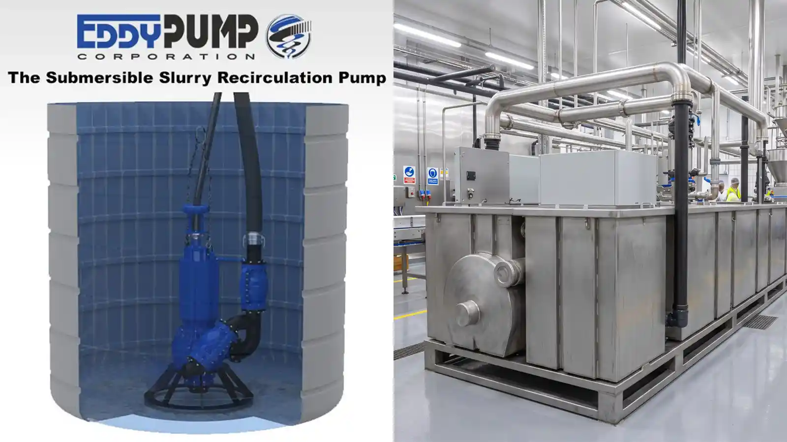
A tank recirculation pump withdraws material from a tank and returns it through one or more discharge nozzles. The returning jets create bulk movement that can blend incoming material, keep heavier solids suspended, reduce settled buildup and disturb floating fats or fibers. Valves can also redirect the same loop to downstream transfer when the process is ready.
This is not the same as choosing a transfer pump and pointing its discharge back into the vessel. A mixing loop is designed around tank dimensions, liquid depth, suction elevation, nozzle elevations, jet direction, piping losses and material behavior. The objective may be blending, solids suspension, cap breakup, equalization or a combination of these.
Turnover Time as a First-Pass Estimate
Turnover time is the number of minutes the pump needs to move a volume equal to the tank working volume once. It converts the operating objective into an estimated flow rate:
Required flow (gpm) = working volume (gal) / turnover time (min)
For a 100,000-gallon working volume:
|
Target Turnover Time |
Calculated Flow |
|---|---|
|
60 minutes |
About 1,700 gpm |
|
45 minutes |
About 2,200 gpm |
|
30 minutes |
About 3,300 gpm |
|
20 minutes |
About 5,000 gpm |
The turnover target is a starting point, not a design rule. Gentle blending may tolerate a longer turnover. Rapid settling, a floating cap or changing feed may need more jet momentum, a different layout or supplemental mixing. Pilot data, operating history and material testing are more valuable than a generic rule of thumb.
Nozzle Velocity and Jet Momentum
A pump can move the calculated volume and still leave dead zones. Flow only mixes the tank when it becomes jets that reach the areas where solids settle or lighter material collects.
In the worked example below, 25 to 30 ft/s was used as the preliminary nozzle-velocity range. At approximately 3,000 gpm, that corresponded to either two nozzles near 5 inches in diameter or four nozzles near 3.5 inches, subject to actual inside diameter and losses. These are example calculations, not a standard nozzle package.
Nozzle Elevation and Direction
A 25 ft diameter by 30 ft tall tank is tall for its width. One bottom jet may sweep part of the floor without turning the upper layer. The worked example used low and mid-to-upper discharge elevations, with jets angled tangentially to create rotating flow. The low jet addresses settled fractions, and the upper-directed jet can help disturb a floating layer.
Suction and Discharge Placement
If the suction opening sits too close to the return nozzles, freshly discharged material can travel straight back to the pump. The result is a strong local swirl while the far side of the tank stays poorly mixed. Keep suction and discharge zones apart, evaluate the lowest and highest operating levels, and confirm the pump has adequate suction conditions throughout the cycle.
How Solids Change the Sizing
The example case describes a design condition of up to 10% solids. Whatever the basis, solids affect sizing in four ways:
- Rheology and friction: A thicker or non-Newtonian slurry can produce more pipeline loss and less flow than a clean-water curve suggests. Test data or a defensible viscosity model should drive the correction.
- Settling fractions: Grit, bone and other dense particles may need floor-directed flow and enough local velocity to prevent accumulation.
- Floating fractions: Fats, oils and light fibers can form a cap that a bottom-only loop may not disturb.
- Power: Density and viscosity change the power required at the real operating point. Driver selection must cover the full range of expected material conditions.
Worked Example: 100,000-Gallon Food Waste Tank
The values below summarize a preliminary application-engineering case. They show how the method comes together. They are not a final design or a model recommendation.
|
Design Input |
Preliminary Example Value |
|---|---|
|
Tank geometry |
25 ft diameter by 30 ft tall |
|
Working volume |
100,000 gallons at about 27 ft liquid depth |
|
Material |
Food waste slurry described as up to 10% solids |
|
Operating objective |
Mixing and keeping solids suspended |
|
Recirculation flow |
3,000 to 3,500 gpm |
|
Turnover basis |
About 30 minutes |
|
Nozzle arrangement |
Two to four nozzles at low and mid-to-upper elevations |
|
Preliminary nozzle velocity |
25 to 30 ft/s |
|
Preliminary nozzle pressure |
15 to 30 psi plus piping losses |
|
Preliminary total head |
Approximately 40 to 80 ft, depending on piping and fittings |
At 3,000 gpm the tank-equivalent turnover time is about 33 minutes, and at 3,500 gpm it is about 29 minutes. The range centers on a roughly 30-minute objective and leaves room for the final system calculation.
The 40 to 80 ft head range should be rebuilt from the final nozzle requirement, actual pipe inside diameter, straight-run length, fittings, valves, elevation, slurry density and rheology. If any of those inputs change, the operating point and required power change with them.
What Buyers Should Evaluate Before Selecting Equipment
Use these criteria to test any proposed recirculation design, whether it comes from EDDY Pump or another supplier.
- Operating objective and production goals: Blending, solids suspension, floor sweep, cap breakup, equalization or transfer, and how the tank fits the production schedule.
- Site and tank conditions: Diameter, height, working volume, minimum and maximum liquid levels, available nozzle locations and access for piping.
- Material characteristics: Solids basis (weight or volume), density, viscosity or rheology, temperature, particle size, grit, fibers, fats and chemistry.
- Slurry behavior over time: Settling and floating tendencies, and how the feed changes through the cycle.
- Duty point: Select the pump at both the required gpm and the calculated TDH on an application-specific curve. Maximum flow and maximum head on a product page occur at different points and should not be combined as one duty point. A published water curve is a controlled reference, not a field prediction for slurry.
- Power requirements: Confirm available electrical, hydraulic or engine power and duty cycle, and verify power across the expected operating range.
- Suction conditions and configuration: A flooded-suction, submersible or self-priming arrangement may fit, depending on tank access, pump location, liquid level, suction lift and site power.
- Maintenance and access: Plan cleanout, inspection access, wear monitoring, shutdown logic and a commissioning test before the quotation is final.
- Total cost of ownership: Compare power use at the real operating point, wear-part life, access for replacement and cleanout downtime, not just purchase price.
Comparing Tank Mixing Approaches
No single configuration suits every tank. This table compares common approaches in general terms. The right choice depends on the tank, the material and the objective.
|
Approach |
Advantages |
Limitations |
Best-Fit Use |
|---|---|---|---|
|
Single low nozzle on a pumped loop |
Simpler piping and fewer nozzles to balance. |
May sweep part of the floor without turning an upper layer or floating cap in a tall tank. |
Tanks where settled solids are the main concern and liquid depth is modest relative to width. |
|
Low and mid-to-upper nozzles, angled tangentially |
Can address both settled and floating fractions and set up rotating flow. |
More piping, valves and nozzles to design and balance. Layout needs engineering review. |
Tall tanks with both settling and floating fractions, such as the worked example. |
|
Pumped loop plus supplemental mixing |
Adds mixing energy where jets alone fall short, such as a persistent floating cap. |
Adds equipment, power demand and maintenance points. |
Tanks where the jet layout alone does not meet the mixing objective. |
|
Transfer pump discharge returned to the tank without a mixing layout |
Lowest design effort. |
No designed jet momentum, nozzle placement or suction separation, so dead zones and short-circuiting are likely. |
Not a substitute for a designed loop when solids suspension is required. |
Where Tank Recirculation Fits, and Where It Does Not
Good Fit
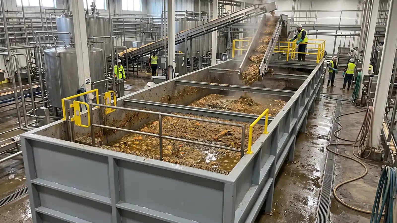
- Food waste and organic waste tanks: Receiving or holding tanks where solids must stay suspended ahead of transfer. See EDDY Pump's Food Waste Pumps page.
- Food-processing and wastewater tanks: Tanks that handle grit, fibers or fats along with solids.
- Tanks with workable access: Enough room for nozzle penetrations and for separating suction from discharge.
- Dual-purpose loops: Systems that switch by valve between recirculation and downstream transfer.
Another Configuration May Be Better
- Very thick material: If pipeline loss limits the flow the loop can develop, rheology data should confirm feasibility before design continues.
- Persistent floating cap: Jets that cannot disturb the cap may need supplemental mixing.
- Limited access: No practical location for nozzles or for separating suction from discharge.
- Transfer only: If the process needs no mixing, the question becomes transfer pump selection rather than recirculation design.
These lists are general. A review of the actual tank and material should decide.
How EDDY Pump Fits a Recirculation Application
EDDY Pump uses a recessed rotor and open internal flow path intended for abrasive and solids-laden slurry. That geometry can be relevant when a recirculation loop must handle grit, food particles, fibers or other material that challenges tighter internal passages.
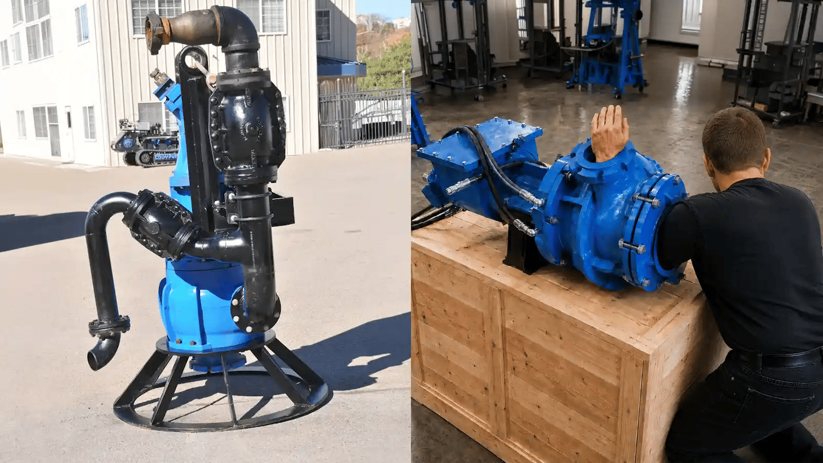
The pump still has to be selected as part of the complete system, including suction conditions, driver, controls, materials, piping, nozzles and maintenance access. Do not choose a model from discharge size or nominal horsepower alone. EDDY Pump's application team reviews the full loop and returns an application-specific custom pump curve based on your material, piping and duty. You can also compare the EDDY Pump slurry pump configuration paths.
Frequently Asked Questions
How Many gpm Are Needed for Tank Recirculation?
Divide the working volume by a target turnover time, then check that the resulting flow, nozzle velocity and layout achieve the mixing objective. A 100,000-gallon tank at a 30-minute turnover is about 3,300 gpm, but the final value depends on the tank, material and process objective.
What Does Tank Turnover Time Mean?
Turnover time is the number of minutes the pump needs to move a volume equal to the working contents of the tank once. It is a sizing starting point, not proof that every zone is mixed.
Is One Discharge Nozzle Enough for a Tall Tank?
Not always. A single low nozzle may sweep the floor but leave an upper layer or floating cap poorly mixed. Multiple elevations or tangential jets may be needed, subject to engineering review.
How Does 10% Solids Affect Pump Sizing?
It depends on whether the percentage is by weight or volume, and on the material rheology, density, particles, fats and fibers. Evaluate the pump curve, power and piping losses for the actual slurry.
Can a Clean-Water Pump Curve Be Used for Food Waste Slurry?
It can serve as a baseline, but it should not be treated as the final field prediction. Slurry properties can change flow, head, efficiency and power, so use an application-specific review.
Where Should Suction and Discharge Be Located?
Place them far enough apart to reduce short-circuiting. The layout should draw from one zone and return flow toward the floor, upper layer or tangential circulation path the process needs.
Which EDDY Pump Should Be Used for 3,000 to 3,500 gpm?
Flow alone is not enough to choose a model. EDDY Pump must also confirm TDH, slurry properties, solids, suction conditions, driver, operating range, materials and installation configuration.
Next Step: Request an Engineering Review
Send EDDY Pump the tank drawing, slurry data, target flow, piping layout and operating objective so the application team can review the complete loop instead of guessing from one number. Useful information to include:
- Tank: Diameter, height, working volume, liquid-level range and available nozzle locations.
- Material: Description, percent solids with weight-or-volume basis, density, temperature and any viscosity or rheology data.
- Particles: Maximum size, hardness, grit, fibers, fats, oils and screening information.
- Objective: Mixing goal and any known turnover, suspension or blending criteria.
- Piping: Suction and discharge elevations, pipe material, actual inside diameter, length, fittings, valves and proposed nozzle layout.
- Power and controls: Available electrical, hydraulic or engine power, duty cycle, control requirements and installation constraints.
- Supporting files: Photos, tank drawings, piping diagrams, operating history and representative material samples or test data.
Next step: Request a custom pump curve and engineering review for your tank recirculation duty.
Related EDDY Pump Resources
- Slurry Recirculation Pumps: common recirculation applications and equipment considerations.
- Food Waste Pumps: additional food-processing and organic-waste pumping applications.
- EDDY Pump Slurry Pumps: available slurry-pump configuration paths.
- Custom Pump Curve: submit material, flow, head and system information for application review.
Technical Sources
- EDDY Pump Corporation, Tank Recirculation Sizing Report for a 100,000-gallon food waste tank, October 20, 2026.
- EDDY Pump: Slurry Recirculation Pumps
- EDDY Pump: Custom Pump Curve
- EDDY Pump: Slurry Pump Family